My ComboSTAR build.


Second ComboSTaR build on the way! See here.

****************************************
ComboSTaR now in use as main HF rig!


September 2010 and my STaR is almost complete, final tweaking to the operational software is still needed and some adjustments making but we're nearly there! I've added a transverter interface (email me if you would like more details about this) and edited the control software to accommodate this. Still to add is transverter PTT switching and rear panel sockets for transverter PTT, linear amplifier PTT and peripheral switching outputs. Still not sure as to adding an analogue S meter, there is space left for one above the four rotary encoders to the left of the touchscreen. Please read on to see just what a journey of discovery building this radio has been...

*****************************

*** Famous Flashing DSP LED springs to life! 9-1-2010 ***
Video here
It sings, FIRST QSO with Angelo W8ERN!

Updated 08-06-10 With Video of TftA 5" LCD screen.

******************************

Designed by Peter Rhodes G3XJP, the PICaSTAR HF transceiver has gained a reputation for true HF excellence with many features not found on any other transceiver regardless of price. Glenn Percy VK3PE had some PCB's commercially produced which have led to the construction of many further examples of Peters design. Glenn has recently had some "Combo" boards produced which combine all the individual 'XJP boards into one. The original PICaSTAR used 'XJP's PICnMIX DDS for control, as technology has progressed, the PICnMIX has been superseded by Ian Sumner G3VPX's TrxAVR graphical display system. I have built the TrxAVR which will use a touchscreen colour TFT display. I originally tested it with a 20 x 4 character display module, then a 128 x 64 graphics module (pictures below). The 5" Colour TFT display that is now fitted looks just too good to be a homebrew radio! Mid December I received my "Combo" board from Glenn, the pictures below show various stages in the construction. As of 16/3/10 it was still bodged together on an old piece of "Contiboard", but now is a bona-fide 150W DSP HF transceiver with touch screen control and supreme performance. I'm sure this project is still going to give hours fun tweaking and modifying, but nowhere near the immense time that Glenn, Peter, Ian, Chris Stake and all the real "STARS" have already put in! Many thanks all. More photo's to come!

Home
About me
The Shack
Guestbook
Links


HF Radio
VHF/UHF Radio
Microwave (23cms)
Test gear


My TrxAVR under test. Atmega processors on TrxAVR My Combo board as of 15-01-10
DSP section of motherboard.

12v RX and 10v LEDs lit on first power up of the partly completed Combo board!

"Magic Roundabout" fully configurable mixer and RF amplifier.
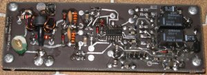
Band pass filter using toroid inductors for the 30m (10Mhz) section and the 10.7Mhz IF trap. Low pass filter to a design by Ray G4TZR, note missing aerial changeover relay now fitted. "Combo" and TrxAVR mocked up on a wooden board and operating as an excellent HF receiver.
01-04-10 Now fitted with a 128x64 pixel LCD graphics module as a temporary display until the TftAVR colour display is available. The 128x64 module gives more information than the previous 20x4 character display. This is just one of many different displays the TrxAVR supports. 20W PA and Low Pass Filter fitted to the rear of the wooden "chassis", now on the air!
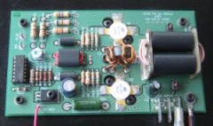
This is my partly constructed Peak reading SWR bridge designed by Ian G3VPX. This will allow my ComboSTaR to show PEP power level, both forward and reflected along with the SWR on the TftA display. A short video showing the DSP display on the TftA LCD display of my ComboSTaR. I really must get round to getting it all boxed up. G6ALU 150W PA stage, a wideband amplifier using 2 x SD1487 bipolar transistors. This forms the output stages of the completed transceiver.
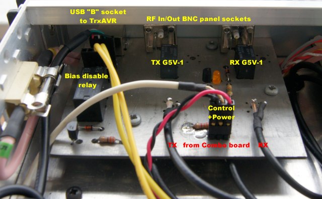
This is a picture of my transverter interface board, an output from the TrxAVR switches via 2N7000s, a G5V-2 relay to disable the PA bias during transverter operation and switch the external PTT line, also 2 G5V-1s which switch the RF paths to the rear panel sockets. I also used this PCB to mount a USB "B" socket which connects to the TrxAVR for use with Hobcat.
 
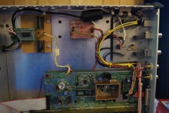
The small board in the top centre of this picture holds two PhotoMOS relays which are switched by the external linear output of the timer section of the Combo board. Only one relay operates at a time being selected by the PTT select output of the interface board above.
 
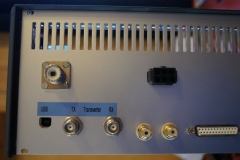
This view of the back panel of the radio shows the USB connector and BNCs for transverter IF input and output. To the right are the PTT connectors for both the transverter and my HF linear, and also a DB25 which is used to connect the PCA-9555 board to the outside world.
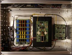
The top of the radio houses from left to right, PeakSWR board, LPF, 150W PA and 20W PA. The bottom of the radio houses the Combo board and from top to bottom, Transverter interface, PTT output board and PCA-9555 board plugged into a board holding two ULN-2803s.